


Frequently Asked Questions
PT. Surya Cakra Mandiri, we aim to provide clear and practical information for engineers, contractors, and project owners looking for reliable cable management systems.
A cable tray is a support system used to organize and protect electrical and communication cables in industrial and commercial facilities.
It provides a safe pathway for cables, improving air circulation, maintenance access, and system organization commonly installed in factories, power plants, and infrastructure projects.
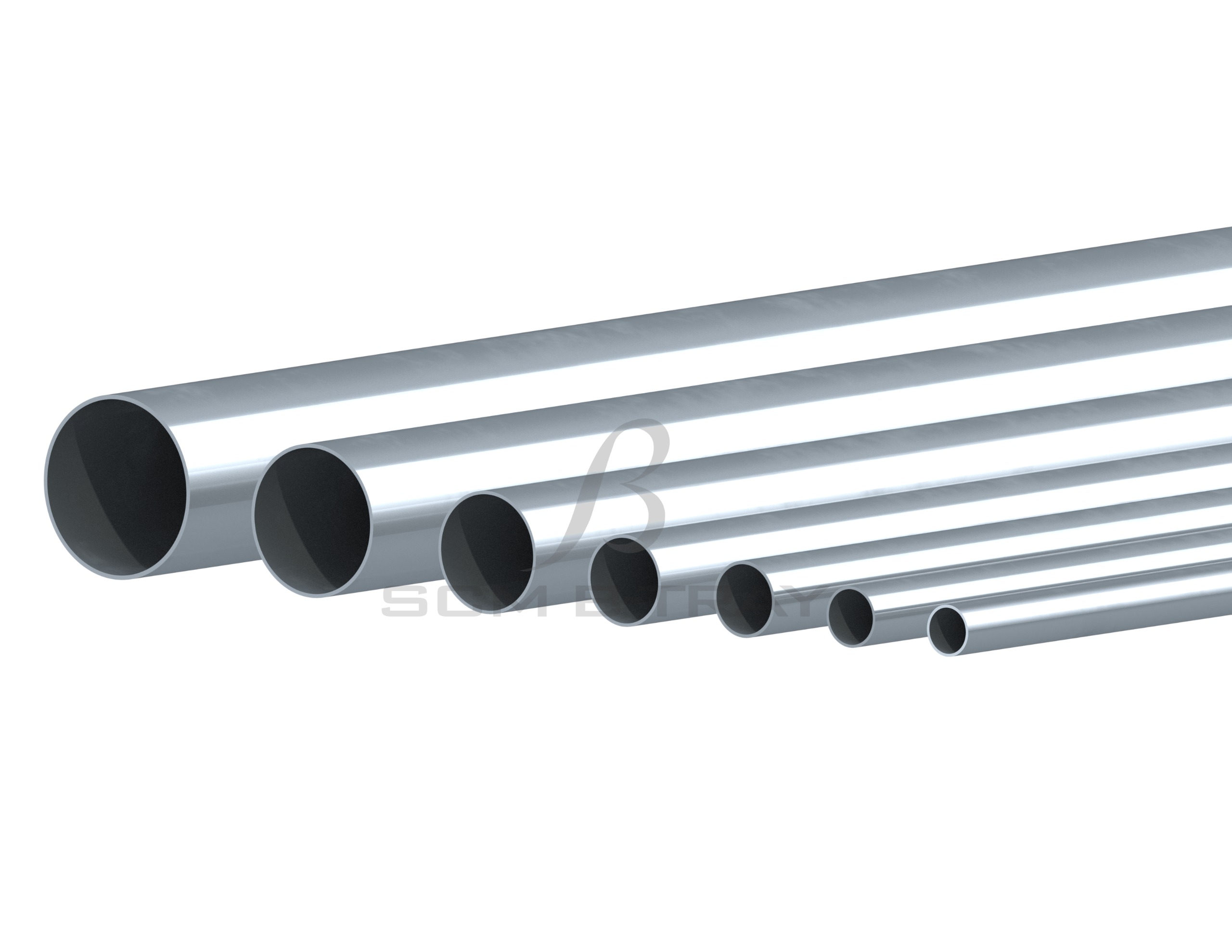
We manufacture cable trays from a range of durable materials, including:
Mild Steel (Hot Dip Galvanized or Epoxy Coated)
Stainless Steel (Grade 304 & 316)
Aluminium (lightweight and corrosion-resistant)
FRP/GRP (for chemical or coastal environments)
Each material type is selected based on project needs ensuring long service life and minimal maintenance.
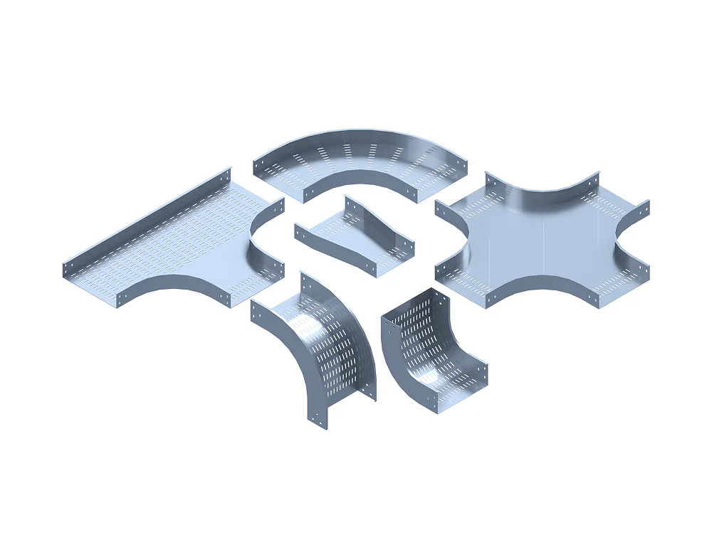
SCM-B Tray offers several types of trays to match various applications:
Perforated Cable Tray: For light to medium load installations.
Ladder Type Cable Tray: For heavy-duty and high heat dissipation.
Solid Bottom Cable Tray: For sensitive or data cables.
Wire Mesh Cable Tray: For compact routing and flexible layouts.
All models are available in custom lengths, widths, and coatings.
Yes. All our cable trays and ladders are produced under ISO 9001, ISO 14001, and OHSAS 18001 standards. Each batch undergoes strict quality control to ensure product safety, load capacity, and finishing quality meet international specifications.
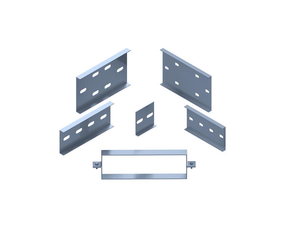
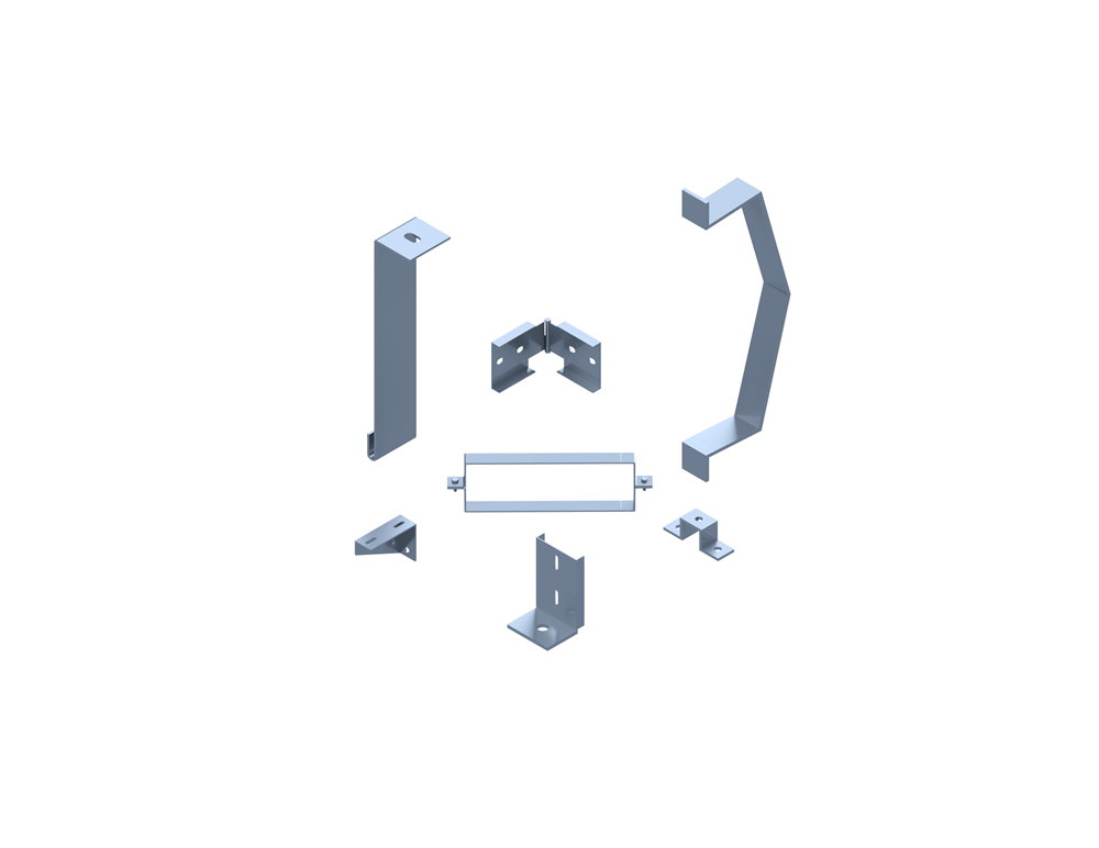
Absolutely. We provide custom fabrication based on your project requirements — including tray dimensions, thickness, material type, and coating (e.g., hot dip galvanized, powder-coated, or stainless steel finish). Simply send us your technical drawings or specs, and our engineering team will design accordingly.